
BACKGROUND
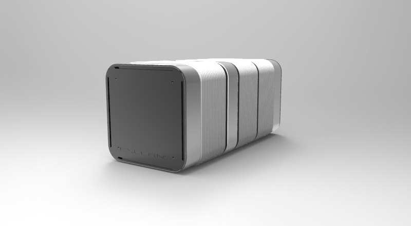
The PowerCenter is a personal power appliance, designed to provide electricity for individuals or individual families, households, or small businesses. In many ways, the PowerCenter is analogous to the personal computer. As the personal computer represented a shift away from centralized mainframe networks, the PowerCenter represents a shift away from centralized power plant grids.
Like the personal computer, the PowerCenter must be small enough yet powerful enough to be practical in the context of individual use. Like the personal computer, the PowerCenter must be located in a convenient location without special rooms or shelters and without extraordinary installation requirements.Personal Power Appliances (PPA) need to be installed if the grid in most countries is going to survive, let alone thrive, or grow. The PPA is a requirement for the “smart-grid”. PPA-like solutions, historically created out of cobbled together products in an ad hoc fashion, fall well short of the functions and practicality of a true PPA. There are sub-utilities that create large reservoirs of electrical storage in-stalled that support a small town or a large neighborhood that mimic the “modulation” function of a PPA. Their effect is minor, they cannot deal with the peak load demands of the individual user. Only a PPA distributed at the granularity of at least the individual family can provide a true solution.
Simply put, the use of energy is chaotic and efficient generation and distribution of energy is most effi-cient when it is a constant. Some device must stand between generation and use. Something like a battery or a capacitor that can modulate the flow of electricity from generation source to user. The key is the size of this modulating device and it proximity to the user.
The PowerCenter is the first PPA, it is the PPA archetype. The PowerCenter is designed for mainte-nance-free deployment to individual families that: one, are connected to the grid but wish to reduce their costs and increase the reliability of their electric power; or two, are connected to a grid but choose not to use that utility or wish to use alternative sustainable resources; or three, are connected to a subpar grid that can neither provide enough power or reliable power for the user; or four, have no grid at all.
The PPA archetype is defined by the following attributes:
• Size deployed to individuals conveniently
• Low maintenance
• Relatively invisible
• Supplying 100% reliable power
• Allows the demand on the PPA to remain chaotic while isolating the source(s)
• Capable of dynamic source selection
• Capable of supplying a utility grid simultaneously, precisely, and safely
• inexpensive, consistence with a typical residential asset
ARCHITECTURE
The PowerCenter is designed as three dependent systems in series. The block diagram illustrates this point. Note that all energy input is sent directly to the energy storage block and all output is supplied from the energy storage block. There is no bypass branch that connects the input directly to the out-put, the PowerCenter is galvanically isolated. In addition, since the storage block stores energy as po-tential energy there is not inductive connection between the input and output blocks. It can be said that they are inductively isolated.
This serial arrangement of the PowerCenter can be thought of as two completely autonomous sys-tems, one for bringing energy to the storage block (i.e. charging) and a second for taking energy from the storage block (i.e. discharging) and delivering energy to the load. This is a critical architectural structure and unique to true PPAs.
The PowerCenter energy storage block is designed to be a hybrid. In fact, the PowerCenter is a ca-nonical hybrid given that each of the PowerCenters blocks are hybrids in their own right. The storage block of the PowerCenter is divided into tiers, where each tier stores energy is a different form or a different technology. PowerCenter storage can be electrochemical, thermal, and kinetic, for example; and the electrochemical tier can have sub-tiers as Li-ion and Lead-acid. This tiered or “polymorphic” architecture gives the PowerCenter storage block the means access storage that can be charged very rapidly and still have access to storage that has very great energy volumetric density.
Polymorphic storage allows the PowerCenter to deal with chaotic input and chaotic output simultane-ously and autonomously. A more homogenous or isomorphic storage system would inevitably con-strain the performance of the input or the output, or both. The input and output blocks use the poly-morphic storage block independently. The input block, however, has a special role in this architecture as it also has the responsibility to move energy from one tier of the storage block to another. In ef-fect, the input block is responsible for transforming the energy appropriately (heat to electrical, or Li-ion to Pb-acid, for example), as well as, the responsibility to optimize the storage to meet and antici-pate the demands of the output block.
Input
The input sub-system of the PowerCenter is designed to accept power for virtually any electrical source. Input hybridization allows the PowerCenter to use AC and DC in a very broad range of voltag-es, frequencies, number of phases, and episodic instability. The input sub-system can be connected to up to 4 different sources of energy via 4 completely isolated and independent channels. From a mechanical point of view, each source is connected to the input sub-system at a “smart junction box” located outside of the PowerCenter enclosure. The smart junction box is referred to as the eUSB giv-en its logical similarity to USB hubs and connections used in personal computer systems. Since the PowerCenter is a hermetically sealed unit, the eUSB provides a user-accessible means to connect sources and loads to the PowerCenter without danger of breaching its seal integrity.
Four electrically isolated circuits conduct power from the eUSB to the PowerCenter. Each circuit goes to the PowerCenter module that houses the input power electronics. This connection is made by a specially designed backplane (referred to as Backplane-M ) containing high voltage, high current, shielded analog and digital signal. The backplane is populated with 16 specially designed controllers arranged in groups of four. Each group of four controllers are comprised of very densely packaged electronics that depend on conduction rather than convection for heat dissipation. Each group of in-put controllers are mounted on a specially-designed plate referred to as a PowerBlade.
A PowerBlade is a 19” rack mounted component that permits heat to be transferred via solid and liquid conduction. PowerBlades are installed in the module by insertion into the 19” rack and the backplane for this module (Backplane-M). Having been inserted, the PowerBlades are connected to the entire system electrically, logically, and thermally.
Each input PowerBlade takes energy from the source, transforms it (300VAC to 80VDC, for example), regulates it, and controls it as required by the PowerCenter’s computer system. Input PowerBlades communicate (as all PowerCenter components do) via the Exulans proprietary bus referred to as the PowerBus . Physically, the PowerBus communicates from the PowerCenter main CPU via Backplane-M; logical communication is accomplished by an Exulans proprietary communication protocol (eComm ) and the Exulans proprietary operating system referred to as the eOS.
All discrete components of the input sub-system communicate digitally to the PowerBus. The input PowerBlades are controlled by analog communication as well. Generally speaking the analog infor-mation is used when real time feedback loops are required. High-speed communication with discrete components is made via proximate MCU devices (digital and analog) which in turn communicate to one of more of the main CPUs. The main CPUs are Single Board Computers (SBUs) modified for Ex-ulans by the manufacturer . The main CPUs can run Windows 7 or Linus as the Exulans eOS is compiled to run on either. At the time of this writing, they run Windows 7, in the long term both will be sup-ported to assure optimal performance and cost. The main CPUs communicate with Exulans “cloud-based” servers. The cloud-based servers can server as a failover redundant replacement for any PowerCenter local main CPU. In other words, failure of a PowerCenter CPU will not necessarily cause the failure of the PowerCenter, the cloud-based server can act in its place even if its connection to the network is intermittent.
The diagram above illustrates how discrete components are controlled by the eOS both within an indi-vidual PowerCenter and remotely by the eOS version on the cloud server. All components mounted on a PowerBlade are built to have PowerCenter required parameter controlled via Exulans protocol and the eOS. For example, the voltage of an input controller must be able to be controlled by the eOS, and at the same time must report its MOSFET temperatures and voltage frequency to the eOS.
Input controllers take energy from the source to which they are connected and, in effect, charge the batteries. Each Input PowerBlade supplies energy according to three parameters: one, the voltage required for proper charging rate; two, using optimal power available from the source; and three, compliment the over input sources according to the logic and priorities determined in the eOS.
Individual Input PowerBlades can charge the same storage medium at the same time while contribut-ed very different voltages and power levels. The technique is referred to as Isolated Asymmetric Charging (IAS ). This technique allows solar panels, for example, to supply 20% of the total energy required by a Li-ion battery where that energy is limited by the maximum efficient voltage (e.g. 97.5 VDC) of the solar panel given the solar conditions at that instant.
As an example, a second PowerBlade whose source of energy is a diesel generator can simultaneously providing the remaining 80% of the energy required at an input voltage of 208 VAC. IAC allows both sources to be used independently and without interference thereby insuring that the requirement of the storage system is met regardless of the local conditions. IAS is enabled by specific hardware archi-tectural requirements designed input the discrete components and enforced by logic on Backplane-M. All Exulans components must be designed to comply with Exulans IAC Specification.
External logic drives the input controllers as opposed to internal circuit topology or embedded soft-ware. Each component and each component manufacturer typically uses proprietary circuitry and embedded software, however, the principal functions and overall control is vested in the externally supplied commands of the MCU and eOS. As case in point, controllers are not designed to charge a particular battery chemistry, say Pb-acid or Li-ion; rather their functionality must be generic enough and responsive enough to charge anything. The algorithms or specific charging processes are found in the main CPU as binary code where it is accessed by the eOS. The manufacturers of storage technolo-gy supply this information to Exulans (see Storage for more details).
Output
The output sub-system of the PowerCenter is designed to provide power for a variety of electrical and thermal load. Output hybridization allows the PowerCenter to send AC and DC in a range of voltages, frequencies, number of phases. The output sub-system can be connected to 3 different AC and DC loads from two AC channels and a third DC channel. One of the AC channels can be configured to send power to a common utility grid or local area micro-grid (see: Grid Supply for more details). Mechanically, loads are connected to the output sub-system at eUSB. The DC channel can also send power to a common DC micro-grid. Three electrically isolated circuits conduct power from the PowerCenter to the eUSB. Each circuit comes from the PowerCenter module that houses the output power electronics. This connection is made by Backplane-M. The backplane is populated by 6 specially-designed inverters arranged in groups of three; and a DC PowerBlade similar in construction to the input controllers. Each group three inverters are comprised of very densely packaged electronics that depend on conduction rather than convection for heat dissipation. Each group of output inverters and controllers are mounted on a PowerBlade.
In the case of a PowerCenter that can supply power to the grid, one of the output PowerBlades is con-figured by the system to receive its synchronization and waveform information from the grid it is sup-plying. If no information is present, that inverter PowerBlade is unable to supply energy since the voltage on the drive side of the isolation transformer is acyclic no energy can be induced on the driven side. If the eOS is instructed to send power to an independently regulated grid, the eOS selects a sig-nal master for each AC PowerBlade. If a PowerBlade has a grid connection and the grid is operational and the eOS has been asked to designate this PowerBlade as a grid supplier, then the eOS connects the PowerBlade signal reference to the grid and not from its internal signal master.
Each output PowerBlade takes energy from the storage block, transforms it, synchronizes it, and con-trols it as required by the PowerCenter’s computer system. Output PowerBlades communicate via the PowerBus and eComm.
Output controllers take energy from the storage block and supply to load. The output PowerBlade supplies energy as demanded. However, the output block is connected to its loads intelligently not blindly. The load management logic is complex and established by the user through the user interface of the Human Load Management (HLM ) software application within the eOS. The output block will supply demand up to its capacity, 150% of its capacity for 30 minutes, and 500% of its capacity for 30 seconds. Beyond those limits, the PowerCenter can exercise control of turning off one load element in favor of another in real time; or, the PowerCenter can alert the user to a conflict and suggest an al-ternative and advise the use of any delay in start-up. Typically, once established, the HLM software operates in the background making choices that it has learned are invisible to the user.
The load is connected in such a way that some of the load elements can be controlled by the Power-Center. The user can prioritize some of the load elements to allow their start to be delayed by the PowerCenter according to the logic and priorities determined in the eOS. The load control mechanism is executed in the eOS and sent wirelessly to the load switching hardware. The PowerCenter supports open-standard residential automation hardware as well as a proprietary set of hardware designed by Exulans.
External logic drives the output inverters and controller as it does with the input block. Each compo-nent and each component manufacturer typically uses proprietary circuitry and embedded software, however, the principal functions and overall control is vested in the externally supplied commands of the MCU and eOS and the HLM software.
Storage
Architecturally, the storage block of the PowerCenter is divided into tiers, where each tier stores en-ergy is a different form. For example, PowerCenter storage can be electrochemical, thermal, and ki-netic. The PowerCenter typically uses at least one electrochemical tier; however this tier can also have sub-tiers such as Li-ion and Lead-acid. This tiered or “polymorphic” architecture gives the PowerCent-er storage block the means access storage that can be charged very rapidly and still have access to storage that has very great energy volumetric density.
Polymorphic storage allows the PowerCenter to deal with chaotic input and chaotic output simultane-ously and autonomously. A more homogenous or isomorphic storage system would inevitably con-strain the performance of the input or the output, or both. The input and output blocks use the poly-morphic storage block independently. A feature of Exulans polymorphic storage is the ability to move energy from one tier of the storage block to another tier by transforming the energy appropriately (heat to electrical, or Li-ion to Pb-acid, for example), as well as, the responsibility to optimize the stor-age to meet and anticipate demand.
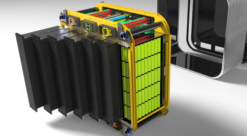
Presently two manufacturers build the PowerCenter electrochemical tier of the storage block to Ex-ulans specifications . Both companies are using Lithium Iron Phosphate cells from different cell sup-pliers. These cell packs are designed and tested to sustain over 10,000 full discharge cycles under PowerCenter specified regimes. We expect PowerCenters to have electrical/galvanic storage MTBF of over 10 years and within the next 18 months, 20 years.
Longevity is achieved by active control. The PowerCenter operating system actively conditions the cells allowing them the longest life possible and then extending that life by performing periodic galvan-ic maintenance of under-performing cells and allowing eccentric cell groups to be isolated from the array and returned when and if they are restored to proper function. Under our performance re-quirements LiFePO and Pb-acid exhibit no significant exothermic behavior adding to their longevity.
A critical parameter of the PowerCenter is “self-maintenance”. For example, an automobile tire that seals a puncture is a very simple form of self-maintenance. Military vehicles, aircraft, spacecraft, and nuclear reactors also employ self-maintenance to various levels of sophistication. The function of self-maintenance can be referred to as homeostasis, and more accurately in more highly developed sys-tems as allostasis .
The PowerCenter is designed to be allostatic. It is designed to regulate its operating conditions under varying circumstances. In the case of the storage block, the eOS must maintain the cells within the de-sign operating temperature envelope. In order to do this, the PowerCenter must “know” about the cell chemistry, therefore it must not only recognize the specific cells in this specific ESM, but it must be able to look up and use the correct information. The eOS must also be able to be given new instruc-tions if the cell manufacturer changes the optimal parameters. Once the eOS understands the regime, it must be able to effect control.
There are three options open to the eOS. The eOS can cool the packs by increasing the air or fluid flow through the electrochemical tier of the storage block. One, transfer heat directly to and from the cells by metered fluid transfer, two increase airflow within the storage module, and three decrease or increase the input or output of energy going to that tier.
The maximum allowed operating temperature is 50°C, if cell packs were to approach this limit and increased airflow or increased fluid flow is insufficient then the eOS would slow the rate of charge to maintain the limit. If the storage block internal temperate is still rising, the eOS would begin shutting down cell-packs one by one until equilibrium is achieved and shunting high priority transient energy sources to other forms of storage.
External logic drives charging hard wired internal circuitry. As a result, controllers are not designed to charge a particular battery chemistry, say Pb-acid or Li-ion; rather their functionality is generic enough and responsive enough to charge anything. The algorithms or specific charging processes are found in the main CPU as binary code where it is accessed by the eOS. The manufacturers of storage technolo-gy supply this information to Exulans.
Battery cell manufacturers can supply their algorithms in three ways. One, man-readable code that can be directly compiled within the eOS or flashed as ROM to the MCUs; two, as binary machine code that is flashed to the MCU by the eOS and stored on the eOS where it can be updated and re-flashed; three, as binary machine code or encrypted code that is resident only on the cell manufacturer’s serv-ers where it can be re-flashed at the MCUs by asking the eOS remotely to perform that function.
In addition to normal charging algorithms, the cell manufacturer can provide the PowerCenter with cell repair and cell conditioning algorithms. The cell manufacturer can add to and update this library of charging functions as extensively as they wish.
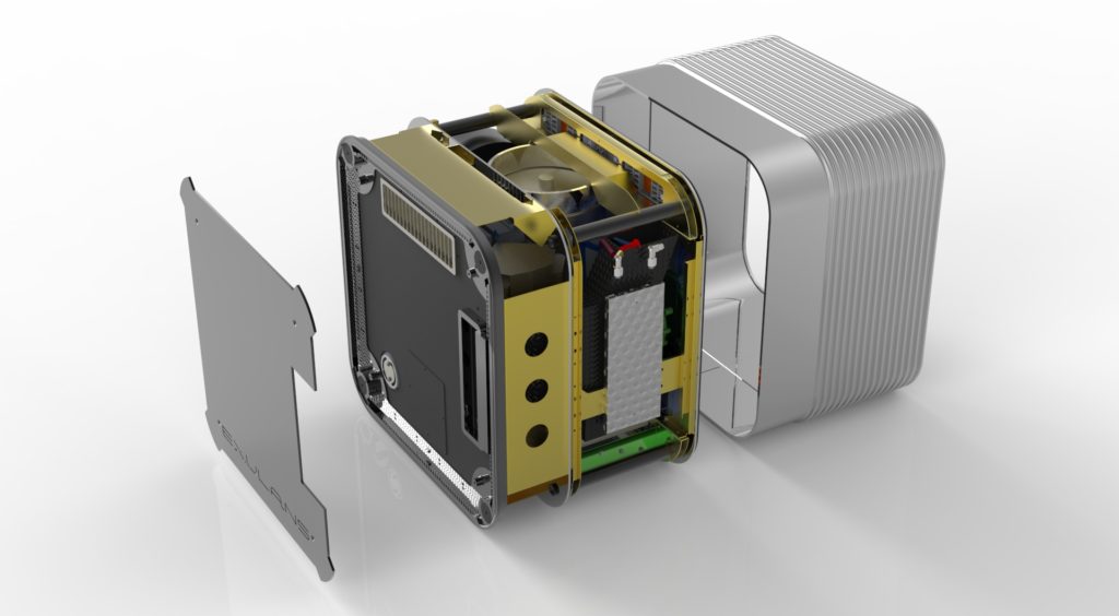
APU
The PowerCenter j10B has an embedded APU; its role is to insure absolute reliability, it is a failsafe de-vice not intended to be the principal source of energy. In fact, the APU is typically the “tertiary” source of energy for a PowerCenter. Generally, the primary and the secondary sources would have to fail before the APU is asked by the system to step in and supply energy. The APU provides energy for a variety of other reasons that have to do with the optimization of performance, generally speaking these are background functions driven by the PowerCenter main computer logic.
In the j10B, this APU is driven by a natural gas internal combustion engine. After 100 years of devel-opment, internal combustion engines still remain the most reliable and efficient (full life cycle) method to convert natural gas to electricity. Soon, we will add tri-fuel engines and multi-fuel (Mil-spec) en-gines to support local user requirements and preferences. Again, the PowerCenter is agnostic. If fuel cells overtake internal combustion, the APU will simply employ that technology where and when it is preferred. PowerCenter systems do not care what the technology is, the system logic simply adapts to the new constraints or rules.
eUSB
(As an aside, the eUSB hub also contains (optionally) an SAE j1776 plug so that an EV can be connected for either charging or auxiliary storage)
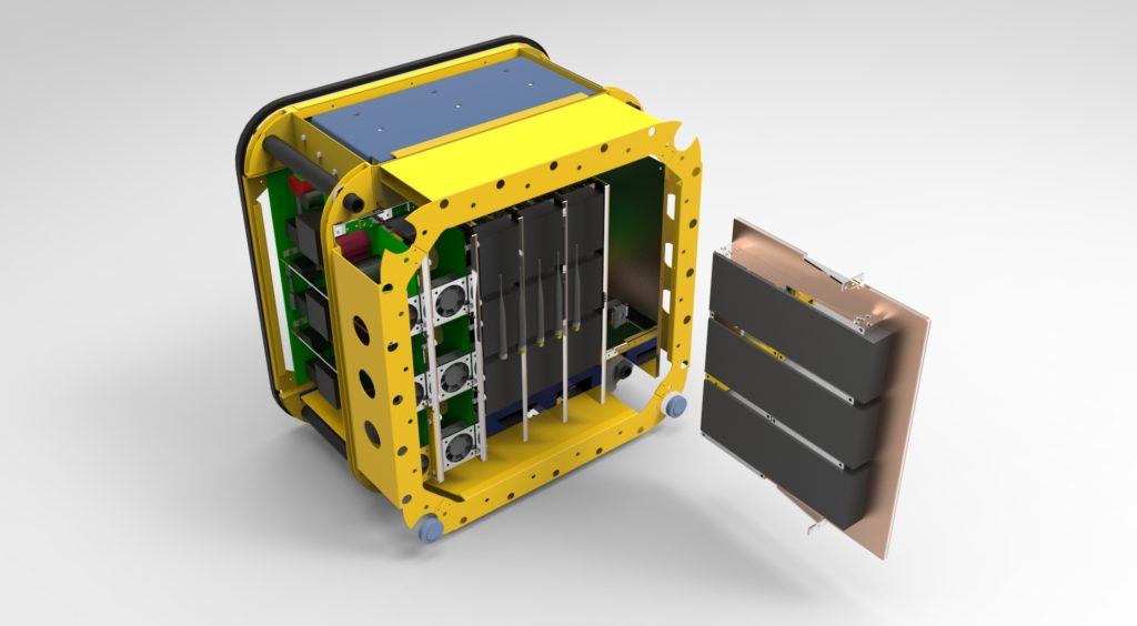
EMM
The EMM of a j10B contains seven PowerBlades. These blades support the power electronics (invert-ers, rectifiers, and controllers) and the main CPU motherboard and ancillary cards. The EMM mother-board is very similar architecturally to a desktop computer. Basically, it controls input and output (en-ergy, as opposed to data); communication intra-system and intra-component, with its remote sys-tems, and with humans; and, monitors its condition and the external proximate environment. Like the desktop computer, the computation is hierarchical with two main multi-core CPUs, a failover CPU, and a number of MCUs that control real time operation.
Ancillary cards can populate the main data bus on the motherboard to allow for differences in hard-ware in the EMM and hardware in the other PowerCenter modules. This unique computer system and O/S allow PowerCenters to be self-aware, plug-and-play compliant, and self-maintaining.
The EMM houses 95% of the power electronics (a bit can be found in the ESM and EIM when required for safety or autonomous operation. The EMM contains 7 2u 19” racked PowerBlades. Blade 1 and 2 mount the output channels (AC/DC, any frequency, any phase). Blade 3, 4, 5, and 6 mount up to 24 isolated channels of discrete input (AC/DC, any frequency any phase). The operating environment of the EMM is maintained 10°C and 50°C. As with the ESM, the O/S has a litany of options for assurance that is a stable environment. The PowerBlade is a very effective way of controlling the temperature of the discrete components. As a result, we (with the hard work and inventiveness of our partners) have achieved very high power densities. All discrete components communicate with the motherboard, physically through a massive 18 layer backplane, and logically through our O/S protocol. All power electronics are digitally controlled through hyper-fast analog linked MCUs for real time performance.